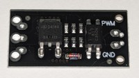
Article pictures
Contains photos and diagrams from the Prusa MK4 smart enclosure guide.
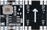
3.3V 5V 9V 12V power module Adjustable MP1584EN DC DC 3A power step down descending output module LM2596 - AliExpress.png
View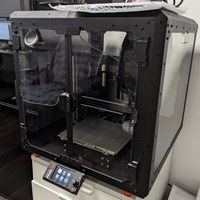
PXL_20240204_175525727.MP.jpg
View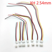
Screenshot 2024-02-04 at 20-23-47 0.85US $ 15% OFF Ph 6.9 jst Ph2.0 Xh2.54 2-10pin Connector Plug Set With Cable 10-30cm.png
View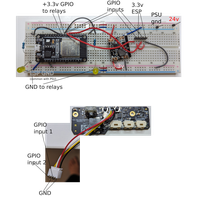
Photographical diagram of breadboard circuit to test push buttons.svg
View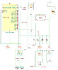
Schematic.png
View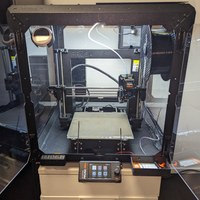
Finished printer enclosure.jpg
View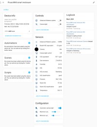
Smart enclosure device screen in Home Assistant.jpg
View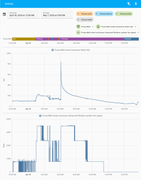
Fan and sensor working in tandem to clean the enclosure.png
View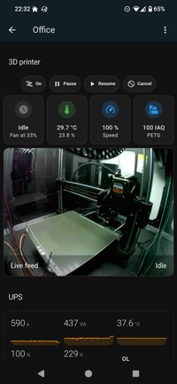
Custom dashboard.jpg
View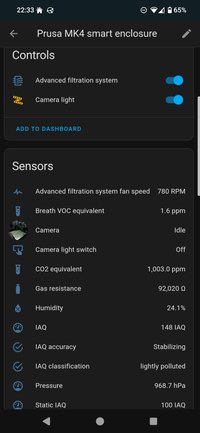
Mobile device view.jpg
View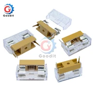
10PCS-Panel-Mount-PCB-Fuse-Holder-Case-w-Cover-5x20mm-With-Transparent-Cover-5-20-Fuse.jpg_.webp
View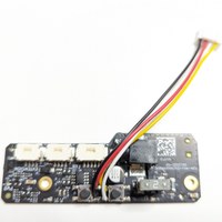
JST connector attached to base board.jpg
View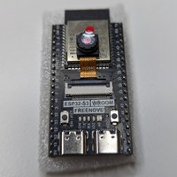
ESP32-S3-WROOM by Freenove.jpg
View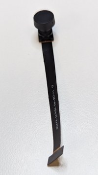
OV5640 camera.jpg
View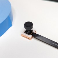
Application of the heat sink to the camera.jpg
View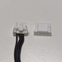
The fan cable before cutting its connector, next to the JST connector it will be replaced with.jpg
View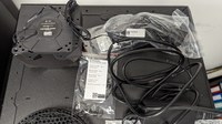
PXL_20240204_175532972.MP.jpg
View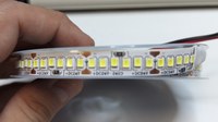
LED strip roll, circuit view.jpg
View
Nearly all components soldered 2.jpg
View
20-Pcs-Double-Sided-PCB-Board-2X8-3X7-4X6-5X7-Tinned-FR4-Prototype-Kit-Printed-Universal.jpg_.webp
View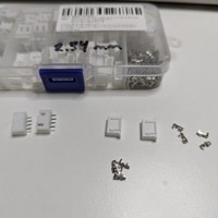
JST pins, connectors and headers.jpg
View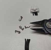
Fan cable already cut, sitting next to wire cutters and JST pins.jpg
View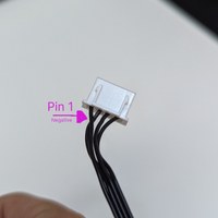
JST connector finished from the top view.jpg
View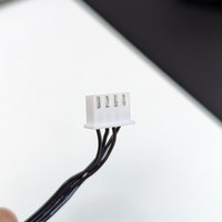
The pin springs firmly locked into their place within the JST connector.jpg
View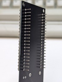
Rear view of the ESP32 placed on the board.jpg
View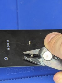
Clipping excess component legs.jpg
View
Nearly all components soldered 1.jpg
View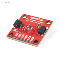
SparkFun Environmental Sensor - BME688 (Qwiic).png
View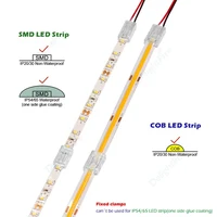
COB-LED-Strip-Connector-Fast-Connectors-For-2pin-8-10mm-2pin-SMD-COB-5050-2835-Single.jpg_.webp
View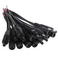
DC-Power-Connector-Pigtail-Barrel-Plug-Cable-2-1mm-x-5-5mm-Male-Female-15CM-Wire.jpg_.webp
View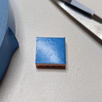
Application of the thermally conductive tape to the heat sink.jpg
View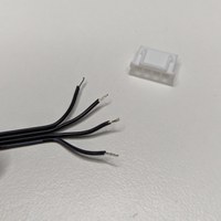
Leads stripped and ready to be crimped onto the pins.jpg
View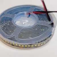
LED strip roll, top view.jpg
View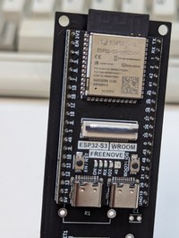
Front view of the ESP32 placed on the board.jpg
View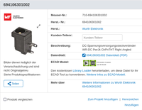
694106301002 Wurth Elektronik Mouser.png
View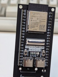
Front view of the ESP32 placed on the board.jpg
View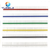
PCB pin strip.jpg
View
Web server of the ESP32.png
View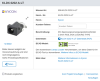
KLDX-0202-A-LT Kycon Mouser.png
View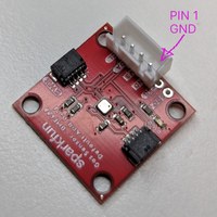
Connector soldered to the BME688 sensor.jpg
View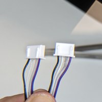
Closeup of the connector cable finished.jpg
View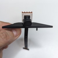
Friction-fit camera, front view.jpg
View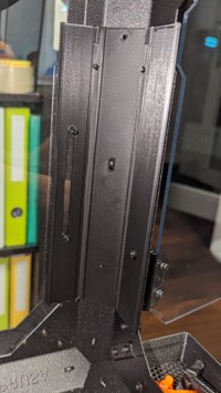
Inner view of the electronics holder affixed to the enclosure.jpg
View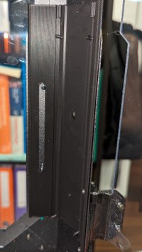
Side view of the electronics holder affixed to the enclosure.jpg
View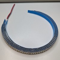
LED strip, cut in segments to size.jpg
View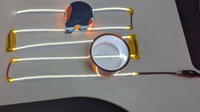
Final test of the LED array.jpg
View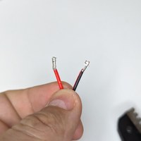
JST XH pins crimped to LED extension cord.jpg
View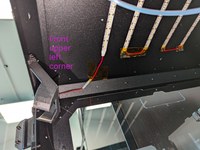
Securing the top of the wire with Kapton tape.jpg
View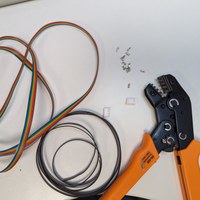
Repurposing 10-lead cable.jpg
ViewTop view of the PCB soldered.jpg
View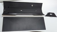
The three parts of the case.jpg
View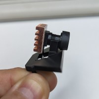
Friction-fit camera, side view.jpg
View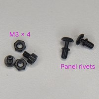
Rivets and screws.jpg
View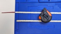
Aligning strips.jpg
View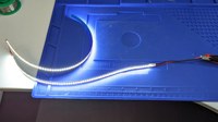
Test two segments in series.jpg
View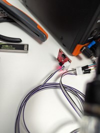
Sensor test after wiring.jpg
View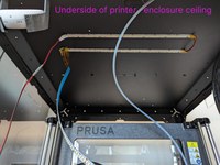
Affixing the first segments of the LED strip.jpg
View
PCB layout.jpg
View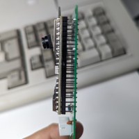
Side view of the ESP32 soldered.jpg
ViewSide view of the PCB soldere.jpg
View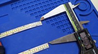
Measuring distance between strips.jpg
View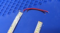
Cutting strip wires to size.jpg
View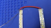
Soldering strips.jpg
View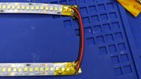
Kapton insulation of exposed leads.jpg
View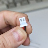
JST XH connector of the LED extension cord, finished.jpg
View
All segments affixed.jpg
View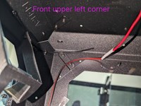
Zip-tieing the top of the wire.jpg
View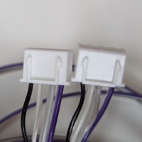
Closer closeup of the connector cable finished.jpg
View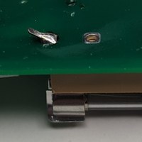
Bent leg of the fuse holder.jpg
View
Screws affixed to the enclosure and the electronics holder.jpg
View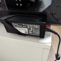
PSU mounted on the PSU holder mounted on the back of the enclosure.jpg
View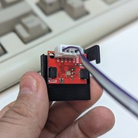
BME688 sensor slid in its pocket.jpg
View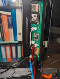
The PCB connected and seated in its holder.jpg
View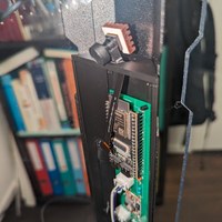
Camera seated atop the electronics holder.jpg
View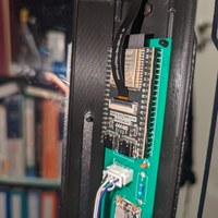
Camera connected to ESP32.jpg
View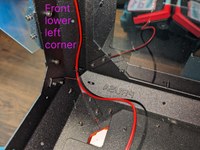
Zip-tieing the bottom of the wire.jpg
View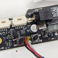
Closeup of the base board wired.jpg
View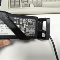
12 volt supply cable routed through the PSU holder loops.jpg
View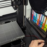
12 volt supply cable routed through the bottom of the enclosure.jpg
View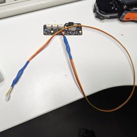
Long shot of the base board and the connector.jpg
View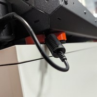
12 volt supply cable routed through the rear left foot of the enclosure.jpg
View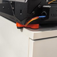
Basic board control cable routed through the installed front panel.jpg
View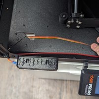
Basic board control cable routed through foot and hole of enclosure.jpg
View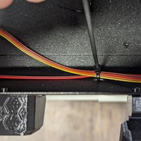
Basic board and lighting cable zip-tied together.jpg
View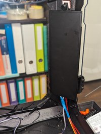
Lidded electronics holder.jpg
View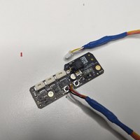
Full shot of the base board and the connector.jpg
View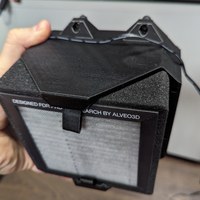
Filtration assembly with cable above it.jpg
View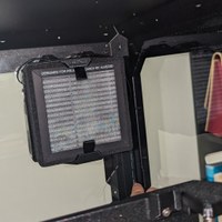
Installed filtration assembly with cable above and to the right.jpg
View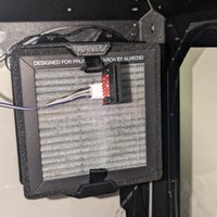
Sensor hanging from fan loop.jpg
View