Contains photos and diagrams from the Prusa MK4 smart enclosure guide.
Making a smart enclosure for the Original Prusa MK4
A fine tutorial you can follow to build your own smart 3D printed enclosure. Electronics, ESPHome, Home Assistant and Creative Commons.

I recently bought an Original Prusa MK4 with its enclosure. While it was quite the job to put everything together, the printer has turned out to be a fantastic purchase — I couldn't be happier with it.

Prusa MK4 printers are fully compatible with Home Assistant — they have their own built-in integration that allows limited control of prints, and lets the user see the status + a preview of the printout. On that basis, I've already made a dashboard for myself, so I can monitor printing time and state.
Since I'll be printing filaments that emit styrene and other noxious gases, in addition to the enclosure I also ordered the advanced filtration system (and its requisite basic board + power supply). The basic board and supply can also power and control an LED strip (24 volts), and the board includes a two-push-button front panel to turn the light and the fan on and off (not depicted here).

Getting this equipment from Prusa Research is only a small part of this journey. The other, more interesting part, is making the equipment work for me with smarts.
What does "a smart enclosure" mean?
This project creates a smart enclosure by implementing the following features:
- Supervise your print:
- A camera should film what's going on, so I can supervise the print through my Home Assistant office dashboard.
- When the camera is actively filming, the enclosure light should by default automatically come on. This is easy to do with ESPHome, since an automation can turn the light on when the camera begins streaming (its frame rate increases), and the light can then be turned off when streaming stops (its frame rate drops to idle).
- Monitor the air quality inside the enclosure:
- I need to know if dangerous volatile gases are being emitted, and how much of that runs the risk of escaping the enclosure.
- These gases should be filtered.
- Improve air quality automatically:
- If the air in the printer is clean, the fan shouldn't run needlessly. If the air is close to clean, the fan ought to run quietly. Should there be no sensor, the the fan should run for the entire duration of the print. Then, the fan should be quiet.
- It should be possible to have the fan spin faster, the more contaminants in the enclosure are detected.
- The fan can be quite noisy at top speed — it should also be possible for the user to define thresholds of contamination that result in appropriate fan speeds.
- Preserve the manual controls:
- "Digital buttons" notwithstanding, the push buttons on the basic board (which attaches to the front panel) should operate correctly, allowing me to manually start and stop both enclosure light and filtration fan as I please.
- Look "stock" after the mods:
- It should look as close to an unmodified Original Prusa enclosure plus the add-ons Prusa Research sells.
Of course, the user experience matters a lot; that's the primary reason why I chose to go with Home Assistant for control of the enclosure.
Before we start
You may want to read my series of guides on powering various electric devices using ESPHome and cheap electronics. This is background knowledge that will help you understand the details of the electronics we'll be building in this post:
- How to control a 24 volt LED strip using an ESP32 and ESPHome
- Govern an LED strip using a MOSFET, an ESP32 and ESPHome
Many of the components mentioned in those guides will be featured in this guide.
What you'll need
This project involves building a circuit that implements all of the features listed above. Here's a list of parts and materials you'll need to obtain. Some are optional — these will be indicated as such both on the parts list and during the assembly process documented below.
ESP32
ESP32s are microcontrollers from Espressif that (1) are very cheap (2) are very versatile (3) consume very little power (4) feature a lot of options for input and output, from GPIO through Bluetooth to Wi-Fi.
For this project, I've chosen the Freenove ESP32-S3-WROOM board, which can be found on AliExpress for a few bucks, and is on Amazon a bit more expensive but with faster delivery. This ESP32 comes with a fairly well-sized antenna, and a connector that accepts both OV2640 and OV5640 cameras. It ships with a tiny OV2640 camera this project will not use, since it's obsolete and produces relatively low-quality pictures.

Camera
I'll need a camera for the ESP32 device. The OV2640 camera that comes with the Freenove ESP32 has decent frame rate, but suffers from bad picture quality. An OV5640 camera with a 120 degree angle will fit the bill in its stead.

Thermal management for the camera
These OV5640 cameras need thermal dissipation because they can get extremely hot, so you'll have to purchase a copper heat sink and double-sided thermally conductive tape. Do not omit the purchase of the conductive tape, even if the heat sinks appear to ship with it — the tape that ships with these heat sinks is thermally isolating, and therefore would be very bad for your camera. You may also substitute the tape for self-adhesive thermal pads you can cut to size.
MOSFET power module
I'll need one MOSFET module, with a D4184 MOSFET. I bought my MOSFET modules from here. These modules are needed because the LED strip requires 24 volts and over 50 watts of power together (supplied by the power adapter Prusa ships), but the ESP32 device "speaks in 3.3 volts" and can only safely do 20 milliwatts per GPIO pin (before giving up the magic smoke). The fan will run with 24 volts, but it won't need a MOSFET module — we'll be using using direct-from-ESP32 PWM control to control the state of the fan.
Make sure the module you get does not come with the screw cable attachments pre-soldered to the module board. You will be soldering only the module onto the PCB, not the cable attachments. The modules I purchased came with the screw cable attachments separate from the board, which was perfect for this project.

DC-DC converter
I'll also need a MP1584EN / LM2596 step-down DC-DC converter, to take the 24 volts of the power supply and convert them into 3.3 volts that the ESP32 device needs. The photos below show how the board looks like almost exactly, but it may arrive with a chip that says 150 instead of 100 — this is fine.

Printed circuit board
This project uses a PCB layout to assemble all electronics components.
Download this PCB layout (the PCB plot files are in folder KiCad electrical design → Plots within the downloaded zipfile), then upload it to a PCB printing business like JLCPCB, then order it printed.
For reference, this is how the finished board (as of version 1.2) looks like:

This is the schematic for the board:

Electronics case
The electronics you'll put together will need a case.
The case consists of three independent friction-fit parts you'll assemble and install within your MK4 enclosure later on.
Download the electronics case from this Github folder — the model file name is Prusa MK4 smart enclosure electronics case.3mf. It contains three parts: (a) the electronics holder, which affixes to the printer's pylon (b) the lower cover, atop which the camera sits (c) the upper cover, which protects the electronics while providing ventilation for the ESP32.
Slice and print the using your favorite filament, at 0.2mm layer height in structural input shaper mode. The 3MF file is directly printable using PrusaSlicer but it should work in other slicers. The 3MF file is preset to print using an Esun PLA+ filament, but you can change that before slicing; while I encountered problems getting the part to print properly with PETG, you might want to do that (or choose another temperature-resistant filament) if you print at high temperatures often .
Important print settings to double-check in your slicer: support angle threshold at 40 degrees, support on build plate only, print all parts sitting on their largest flat contiguous surfaces.
Pro tip: the filament that will looksmatch to your enclosure is almost certainly Prusament Galaxy Black.

Screws and nuts
To affix the electronics case to the enclosure, you'll need two M3x4 hex head screws and matching nuts (maximum 3mm thick). You may get away with using the excess rivets that shipped with your Prusa MK4 enclosure, but since the enclosure also ships with excess M3x4 hex screws and nuts you might as well use the bolts and nuts. The screws have two key advantages over the rivets: they don't loosen over time with print vibration, and they look stock in the final build.
If you only have M3x8 screws, and you are careful, you can cut them up to half their length and they will work too.

Lighting
The enclosure needs lighting. To that effect, you'll need a 24 volts DC LED light.
You can purchase a fully assembled and working LED light, ready to be mounted somewhere within your enclosure, if you so prefer — this will save you a lot of labor. Just make sure that the LED is 24 volts and consumes less than 1 ampere. Prusa Research sells an LED strip that can be mounted easily to the enclosure.
For this project, I bought a 5 meter self-adhesive LED strip that works with 24 volts DC and can be cut to size. This will work perfectly with the power supply sent by Prusa Research, and will illuminate the printed parts from above.
I will not be using the entire roll! Rather, I'll cut as much of the power strip I think it's necessary to illuminate the enclosure well for the camera to work at night, and then strategically place the segments (interconnected in series) on the roof of the enclosure to illuminate the printout.
For the record, at 24 volts supplied, the roll consumes about 2 amperes — just this load alone would overwhelm the power supply that came with the basic board. Whichever LED lighting you choose, be sure not to exceed 1 ampere at its final sizing.


Never power the strip while on its roll for more than a few seconds at a time — you can overheat and burn it that way.
Wiring
Some wiring will be necessary as well. To wit:
- Get some insulated two-lead 22AWG wire to bring power to the lighting. One of the sides will need to be soldered (or crimped) into the input wiring of the lighting; the other side will hook up to the PCB using a JST XH connector (see below).
- Get insulated ribbon cabling to attach the other, non-power-demanding components. I bought this 10-lead ribbon wire from Amazon. This cabling does not need to be thick-gauge since it will not be carrying high currents. Any ribbon wire with 4 leads or more will work here — you will only use 4 of the leads when making cabled interconnects.
Optional: connector modules for DIY LED array assembly
I will use short segments of 22AWG wire to solder LED segments in my DIY LED strip. This could be a lot of work you may want to avoid.
There is a solution to avoid this soldering labor: these solderless LED strip connection modules exist and you can purchase them. Make sure you purchase the right kind of connection modules — in my case, the strip I will use is 10mm wide so I will purchase get the 2-pin 10mm units.
To make your life a little easier, you can choose to get both strip to wire as well as the strip to strip modules — but anything that lets you crimp a two-lead wire to the LED strip is fine.

Headers: sockets and connectors
Get a kit of JST XH 2.50mm pitch male connectors, female through-hole solderable headers and pins; these will be used to hook up the front panel and the fan. This is what I did: I bought this header / connector / pin JST crimp kit and the JST header crimping tool.
With these supplies:
- stable connection points can be created on the PCB,
- the 4-wire and 2-wire cables (of the exact lengths we need) can be created, and
- the connector that ships with the fan cable can be replaced with the JST-XH connector that the PCB requires.


Auxiliary PCB parts
Get PCB pin strips to attach some components to the PCB board. These pins fit the holes of the breadboard as well as the components, can be broken off individually, and any excess length is easily cut with wire trimmers.

Get a female 5.5 / 2.1 through-hole barrel socket to take up the 24 volts produced by the Prusa Research power supply. Alternatively, you can purchase 5.5 / 2.1 mm barrel sockets with built-in cables. Here are photos of a through-hole barrel socket and wired barrel sockets / plugs:


I will need a fuse holder and a 2 amp fuse. The fuse holder can be obtained here (it's depicted below) and the fuses can be these (but it's on you to check that they really do blow at 2 amps). The fuse is important for safety. They usually come with protective lids, but you won't use the lid on your project's fuse holder, since the electronics case already has a lid.

Air quality sensor
Optionally, you can add an air quality sensor to your project.
While any I2C sensor with 3.3 volt power should work, I've chosen the BME688 from Bosch, in convenient SparkFun packaging form. The project will include code to enable this sensor, should you get one for your own setup.
Do not touch the silver metal casing of the sensor at the center of the board.
.png")
You can use any air quality sensor you prefer (if, for example, you care about particulate matter instead of gases). There are many sensors good for ESPHome use, but any sensor you choose must be 3.3 volt-powered and must support the I2C communication protocol. Of course, if you choose a different sensor, you will have to alter the ESPHome programming of your smart enclosure to work correctly — refer to the ESPHome documentation for your chosen sensor. You can even use two sensors (if you go out of your way to make a splitter cable for the I2C connector) as long as the two sensors have different I2C bus addresses.
If you choose the same sensor specified by this project, then your sensor will need a case to affix it to the air filter. Download the file Prusa MK4 smart enclosure BME688 sensor pocket holder.3mf from this Github folder. The 3MF file is preset to print using PETG as material, but you can use PLA+ as well without issues. There is a corresponding FreeCAD file for the pocket holder in that folder as well.
Passive components
In addition to the parts above, you'll need a few electronics components that can be found pretty much anywhere online (and would be available in Radio Shack, if Radio Shack still existed in its original form):
- One through-hole resistor 5000 Ω (5K1) in value, and another through-hole resistor 4600 Ω (4K7) in value.
- They will be used to limit current going to the PWM pin of the fan, and current coming from the tachometer pin of the fan.
- In a pinch, two 4600 Ω resistors would work, and two 5000 Ω resistors might work.
- One through-hole ceramic non-polar 151 (150 pF) capacitor.
- This cap will filter transients in the PWM signal for the fan.
- Two through-hole Schottky diodes, part number 1N5819.
- They will help rapidly unload reactive currents (back EMF spikes) from the motor of the fan and the LED strips, when they are switched off.
- This blog carries a tutorial on how to govern high voltage loads using relays, which explains back EMF spikes — you should read it.
Parts from Prusa Research: PSU, basic board, and filtration system
From Prusa Research, you'll need the PSU, the basic board, and the advanced filtration system. I don't include photos here, because these are better photographed on Prusa Research's site (see the links on this paragraph).
Optional: Mounting bracket for the PSU
Additionally, you will need the PSU mounting bracket, which is 3D-printed. Depending on which PSU you have, you need to choose which bracket to download from the download page: the file EXTERNAL-PSU-bracket-DELTA is for the Delta PSU, and the EXTERNAL-PSU-bracket-XP is for the XP PSU. The files suggest you should print the bracket using PETG filament; that duly noted, I am pretty sure printing it with PLA would be OK too.
Print the bracket that suits your PSU.
Tooling and supplies
You will need a soldering iron, some flux you can apply onto the PCB, and a roll of rosin core solder.
I recommend you own a simple multimeter with alligator clips, and some DuPont wires. These will be extremely useful to test for voltages and continuity. Without a multimeter, you are generally flying blind. Cables with retractable hooks on both ends will also be very useful for testing.
As far as other tools go, you will definitely need wire cutting pliers. Have a pair of thin needle-nose pliers too — you'll use them to crimp JST XH pins in some circumstances.
Have some Kapton or electrician's insulating tape around, as well as some heat-shrink tubing suited for AWG22 wire.
Software
Finally, on the software side, we'll use ESPHome. ESPHome is software that makes it extremely easy to program these ESP32 devices; instead of having to hand-roll C++, all I have to do is put together a YAML file (which I'll supply below) and this puts together all the functionality we need from the circuit, almost straight into the ESP chip.
You might prefer to install the ESPHome add-on on your Home Assistant instance; if you don't have Home Assistant and don't plan to use it, you can manually install a standalone copy of ESPHome on your computer. Either way, you'll need ESPHome on a computer with an USB type C port in order to program the ESP32.
Programming
Once you have obtained your ESP32, you are ready to program your device.
Prepare the sketch
- Create a new device sketch in ESPHome, selecting any of the ESP32 devices there. Name the sketch Prusa MK4 smart enclosure.
- Go to the editor of the newly-created sketch, then copy the code that ESPHome generated for you into a separate, blank text editor.
- Replace the code in the ESPHome editor with a copy of the sketch on Github code that follows below.
- To get the raw code into your clipboard, click on the copy button next to the Raw button at the top of the code listing on that page.
- Add your encryption key to the sketch:
- Rescue the API encryption key (
api: encryption: key:) from the separate text editor via copy. - Paste it into the sketch within the
substitutions:section value titledapi_encryption_key.
- Rescue the API encryption key (
- Add the OTA password to the sketch:
- Rescue the OTA password from the separate text editor via copy.
- Paste it into the sketch within the
substitutions:section value titledota_password.
- You may want to enable the access point (
ap) underwifi:in case the device fails to connect to your wireless network. Search in the file forap:. - Find all the comments in the sketch (all the lines that start with
#) and follow the instructions in the comments.- Particularly, the sections that indicate things must be commented or uncommented depending on the presence or absence of an IAQ sensor, as well as the section where the text sensor for the printer is defined.
- The defaults should work well if you do have a sensor with an IAQ index named
iaqlike the one this project recommends.
- Save the sketch in ESPHome.
Flash the sketch for the first time
Once you have saved this, upload it to your ESP32 via USB:
- Connect the device using an USB type C cable. Try not to touch any of the I/O pins, and be sure you don't discharge static onto any part of the device.
- Make sure your computer detected the device and installed drivers for it.
- Press the Install button at the top of the editor.
- Select the flash option Plug into the computer running ESPHome Dashboard.
- Wait until it is uploaded.
- Wait until you see logging output.
- If you do not see logging output within a minute (it can happen with USB serial ports) exit from the log window, go back to the main ESPHome interface, and push the LOGS button on the Prusa MK4 smart enclosure item, to then connect to the device via Wi-Fi.
Once the device reboots after flashing (assuming you left the web_server component uncommented in the sketch) you should be able to access the ESPHome interface on your device through your Web browser at http://the-ip-of-your-device/. The IP and MAC addresses of your device should be registered with and discoverable through your wireless router. The logging output you'll see onscreen after flashing the device will also show the IP address of your device. I recommend you tell your wireless router to give the device a static IP address to prevent problems in the future. The Web interface of your device should look somewhat like this:

From this point on, you can use ESPHome to reflash your device directly via Wi-Fi. There is no need to keep the device connected for flashing — only for power.
Add the device to Home Assistant
If you are using Home Assistant, the ESP32 device should have automatically appeared as addable. Add it to your Home Assistant, using the API encryption key written in the sketch.
Being a Home Assistant user, it is highly recommended to remove the web_server and esp32_camera_web_server components from the sketch after testing, if you don't plan to use them. These components open access up to your enclosure to anyone on your network without authentication. But there are valid use cases to keeping them around — e.g. AI monitoring of your prints from a Frigate instance or periodic analysis of failed prints by Claude — it's your call.
I see errors on my ESPHome logs?
At this point, none of the electronics you'll drive with the ESP32 are connected, so none of the controls onscreen will work; in fact, you should see errors (such as camera not found or sensor not found) on the logging output that ESPHome presents. Be patient, we're about to get to business.
Build the hardware
Prepare the camera
Follow these steps to prepare the camera for use:
- Do each following step with the camera lens cover on.
- Many of the heat sinks for small devices usually come with a double-sided 3M backing tape. You need to remove every trace and bit of that tape, because that tape is actually thermally isolating. Use isopropyl alcohol or another solvent to clean the back of the heat sink.
- Place the heat sink upside down.
- Cut an appropriately sized square from the thermally conductive tape, and firmly affix it to the heat sink. Make sure no bubbles are under the tape; start over and repeat the process if you see any. Cut any excess protruding from the sides of the heat sink.
- Peel off the other side of the tape, and affix the heat sink with the tape squarely in the center of the back of the camera (which should have a metal backing). Keep the camera covered with its built-in cover while you do this, so as to not impregnate the lens with grime or skin oils.


Once your camera has its heatsink properly installed, friction-fit the camera onto the camera support part of the electronics case you printed. Thread the ribbon cable of the camera through the vent hole at the top of the camera support part. The fit should go around the neck of the camera, it should be snug, and it should look like this:


Prepare the fan
Since the fan comes with a CLIK-MATE connector, but we're using JST XH connectors in this project, we are going to have to re-pin the cable, and then insert the pins into the JST connector.
A quick primer on making JST connectors well
The process is somewhat complicated, requiring the specialized JST crimping tool to do it fast, although it can be done (very carefully and very slowly) with a pair of thin needle-nose pliers as well. If you're using the tool, here's a video full of macro shots that teaches you in detail how to do it; the process described is as follows:
- Cut the existing connector from the four-lead flat cable of the fan.
- Separate the four leads from each other roughly an inch long.
- Strip the end of all four leads to expose 2 millimeters of wire strands.
- For each lead, do as follows:
- Carefully insert the lead from the side of the long wings until the lead "stops".
- The bare wire must be where the short wings (at the center of the pin) are, and the insulation must be where the long wings are.
- Do not bend the strands or over-insert the lead — this will interfere with JST connection mating and can cause a short circuit.
- Crimp the wings of the pin around the lead using your tool or needle-nose pliers, making sure that the end of the pin (square-shaped, with a tiny spring) is not damaged in any way.
- Ensure that the short wings have tightly clamped on the bare wire strands, and the long wings are tightly wrapped around the insulation of the lead.
- Tug on the wire with reasonable force, while holding the pin firmly. The lead should not come out of the pin. If it comes out, start over again from the top.
- Insert the finished pin with lead into the JST socket.
- The crimped pin goes into the channel only one way: the tiny spring aligned with the window (tiny hole) at the end of the bottom of connector, where the spring will lock and it will no longer be possible to remove the pin.
- The spring of the crimped pin should somewhat click into place once it gets all the way in.
- You may want to use the tip of a paper clip to push the pin all the way in.
- Carefully insert the lead from the side of the long wings until the lead "stops".
The order in which the pins must be inserted is as follows: with pins 1 to 4 of the connector facing up♣, the negative lead (that's the lead with dashed white markings on its insulation) goes into pin 1 of the connector. Then the rest of the pins go in the same order as they are on the cable.
Here is the instruction video on how to use the crimping tool I mentioned earlier. This man seems to be a pro at this! I failed numerous times until I got it right:
Here are some photos of the process; I have omitted my many failures just to prove it can be done:


Fan pinout
For reference, this is the pinout of the fan (with its corresponding position of each cable in the JST connector):
- Pin 1 is the negative terminal.
- Pin 2 is voltage in (24 volts). It should be to the right of pin 1.
- Pin 3 is the tachometer output, to measure fan speed.
- Pin 4 is the PWM input, to govern fan speed.
Test the fan spins correctly
Connect 24 volt power to pin 1 (negative) and pin 2 (positive) of the fan's JST plug. You can use the DuPont lead trick to supply power to the JST plug.
If you use the Prusa Research PSU to supply power, remember that the outside of the barrel plug is negative, while the inside of the plug is positive (double-check this with your multimeter and the polarity label printed on the PSU). To safely test the fan using the PSU, you'll need a barrel plug cable with bare leads, as well as a way to clip each bare lead to a DuPont lead that can be inserted into the fan plug's tiny holes. Be very careful not to short the bare leads as this will burn your PSU.
When you supply power to the fan this way, the fan should spin at its maximum speed sucking air through the filter and pushing air through the exhaust holes. If the fan doesn't spin or it spins backwards, you have an issue you must fix in your connector.
Prepare the lighting
Ready-to-go lighting fixture?
You may have chosen a single high-power 24 volt LED, or a finished 24 volt LED fixture to mount to the ceiling of your enclosure, or even the LED fixture sold by Prusa Research for their enclosure. All of those are fine choices.
All you must ensure in this case is that the wiring of the LED is properly terminated with a 2-pin male JST XH plug, where pin 1 is ground (negative) and pin 2 is (positive) 24 volts.
Do-it-yourself LED strip?
I chose to go the self-sticking LED strip route, so I have to actually prepare a lighting array using the LED strip. My plan is to light the printing area of the Prusa MK4 (when the printer is running) with an el cheapo divisible LED strip I purchased, which means I have to affix segments of the strip in a roughly square configuration inside the ceiling of the printer, right above that printing area.
To maximize the amount of lighting covering that area (after some current measurement experimentation) I chose to go with 5 segments (each 30 cm wide) of 12 LED blocks (6 LEDs) each. Given each strip is 1 cm wide, if we allow for 4 cm between strips, that creates a rectangular shape 30 cm wide (left-to-right) and 36 cm deep (front-to-back). This yields about 0.9 amperes of power consumption — well within the safe margins for the cabling and headers this project specifies.
Cut the strips to size:

Solder the strips in series:
- To minimize cable run, I elected to place the input leads of the strip such that they are closest to the the front left corner of the enclosure's top panel (on the underside).
- The segments will be stuck to the inside of top panel in an orientation upside down of how they are soldered together.
- This means the segment with the input must be to the right and at the bottom (closest to me) on my soldering workstation.
- Thus, when mounting, I can flip the entire array upside down, and the input lead will be where I need it to be.
- See the final test photo below to understand the final arrangement of the soldered LED segments.
- When soldering, I used my calipers to space the strips out consistently, then cut and stripped the cabling accordingly to conform to this size.
- You may choose to use a wooden template or some other sort of more precise spacing mechanism.
- Importantly, when soldering, you must solder strips in series: the negative rail of one segment must be connected to the negative of the other segment, and the same is true for the positive rail.
- This has interesting implications for the connection leads and the orientation of the strips — between two strips, one of the leads (either positive or negative) is always shorter than the other, and strips must be oriented in alternating rotations.
- Note that the insulation should not be stripped more than 3 millimeters — cut excess stripped wire to size. Finally, be careful not to move the lead as the solder is solidifying; you may get a weak connection if it does.
Here is the process I went through, depicted in photos:


I recommend you test every successful soldering step using a 24 volt power supply. The last thing you want is to discover that you have to redo everything because a connection in the middle of the series is bad.

After testing, I insulated the exposed solder points using Kapton tape, carefully lifting a short amount of the adhesive backing from the segment before insulating the back of the solder points. Other methods of protecting these solder points include standard electrical insulation tape or some other non-conductive medium like hot glue. I verified with my multimeter that the tape is insulating (some variants of Kapton tape can be conductive).

With the LED array complete, I tested it:

I then made an extension cord that will connect the LED array to the PCB header designated for the lights (LEDSOCKET1), by attaching a JST XH 2-pin male connector to one ond of the cord. The pinout is trivial: black (negative) to pin 1, red (24 volts positive) to pin 2.
A note about cable length: because of where I was planning to place the first LED segment, I calculated that the total cable run only needs to be 141 centimeters minus 9 centimeters (the length of the input leads) which equals 132 centimeters. In my build, I ended up making this cord 135 centimeters long just in case, but (based on the placement of the first LED segment) this led me to have a 13 centimeter slack at the side of the connector; in retrospect, 122–123 centimeters would have been perfect. Expect the total cable run length to vary for you too.
Since the typical LED cable has thicker insulation than signal-carrying cables, I had problems attaching the pins using the crimping tool as the pressure it exerts was cutting my leads outright. I ended up having to carefully crimp the JST XH pins using thin needle-nose pliers under a magnifying glass. I think the needle-nose pliers job turned out quite well — I tugged on the pins and none came off.


The final step is to mate the extension cord to the LED array by soldering it.
- Insulate the connection.
- Prior to soldering, insert some heat-shrink tubing around each lead of the extension cord.
- Once the soldering is done, slide the heat-shrink tubing over the solder point of each leg, then heat up the tubing to make a tight insulation around the lead.
- If you don't have heat-shrink tubing, you can accomplish insulating the two wires from each other by rolling electrician's tape around each individual solder point, then around the junction. This is harder to do than heat-shrink tubing insulation.
- Pay attention to the polarity when soldering the leads! Black -> pin 1. Red -> pin 2.
Prepare the sensor
To hook up the sensor, you need to do two things:
- Add a JST XH 4-pin socket to the sensor.
- Create a 4-lead cable, 10 centimeters (4 inches) longer than the cable of the filtration fan, ending with 4-pin JST connectors on both sides.
Soldering the socket to the sensor is easy. Just make sure that pin 1 in the socket is soldered to GND on the sensor; pins 2 will be power (3V3), 3 SDA and 4 SCL.

Since I purchased a 10-lead cable, I repurpose 4 of its leads for this use by carefully prying four leads apart from the rest of the cable, making sure not to nick the insulation of any individual lead. After separation, this is how it looks.

Strip 2 mm on both sides of each lead, and crimp JST pins to each stripped lead end. I recommend that, once you're done crimping all pins, you test for continuity of every lead at both sides before inserting the pins into their respective connector. Don't forget to tug on the pins to see if the leads are properly secured. Doing these things before inserting the pins will save you from having to redo the connectors later.
As we did before with the fan, insert the pins into the connectors such that pin 1 is always leftmost / connects to ground when the connector's friction locks are facing up. Note how the color codes of the wires match on both connectors.


At this point, you may want to test continuity on each lead again, using your multimeter and some DuPont jumper wires.
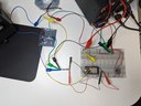
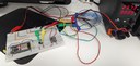
Test the sensor
The sensor should power on (an LED should turn on) when supplied with 3.3 volts to the 3V3 pin and grounded on the GND pin. You can rig on a breadboard the 3.3 volt power converter to a 24 volt supply to generate the necessary power for the sensor, or you can use as supply the 3V3 and GND pins on your ESP32 device while supplying the ESP32 device with 5 volts power via USB.

Wire up the control buttons on the basic board
We'll use the basic board as a mechanism to control fan and lighting manually. For that, we need to hook up those buttons to our ESP32 device; this is the first step to accomplishing that.
Carefully solder the top and bottom pins of each button to a 4-lead cable (which should be 70-71 cm long, and should not be thinner than 26AWG).
Following that, crimp JST XH pins to the other side of the wires (same as you did before with the fan), and insert those pins into a male JST XH plug.
Pay close attention to how you solder the wires and make the connector:
- Pin 1 and pin 2 of your connector (ideally, black and red wire) must attach to the top and bottom leg of the fan button. The name of the button is silkscreened in the back of the board.
- Pin 3 and pin 4 of your connector (white and yellow in the picture below) must attach to the top and bottom leg of the LED button.
- Pin 1 is the leftmost pin when the JST XH connector has the dual friction fit locks facing up. The flat side of the JST XH connector with the windows for the pin springs is the bottom side.
- By convention within this project, pin 1 of JST connectors is always ground / negative. This particular hookup is no exception.


Test the buttons
To test for continuity, insert pin headers / DuPont wires into pins 1 and 2 of the JST XH connector, and attach the other side of said wires or pins to your multimeter's alligator clips. Set the multimeter to resistance / continuity test mode. When depressing the fan button, there should be continuity (if your multimeter beeps on continuity, it should beep). Repeat the test for pins 3 and 4 with the LED button.
Ignore the rest of the board. We don't care about its electronics any more.
Place and solder all parts on the PCB
Before you start, make sure you don't have the camera attached to the Freenove ESP32. Besides the annoyance it would cause you while soldering, the ribbon cable of the camera is delicate and can break or burn during soldering. Be careful when popping open the brown cable clip holder that secures the camera ribbon cable — those clips are delicate and can break if an uneven pull force is applied to them.
With the PCB, place each component according to the schematic, and solder each pin of the component that the schematic wants soldered on its respective through-hole.
Solder components from shortest to tallest. Avoid soldering e.g. the fuse holder first, since the fuse holder is the tallest one, and a soldered fuse holder will give you trouble soldering all other components, as the board will be upside down while you solder. The one exception is the ESP32 — solder it last. Try to solder it without inserting it too deeply, to provide clearance for the USB ports, should you need to reflash it later.

When you solder the fuse holder, please be absolutely sure its base is flush with the board. The fuse holder is the tallest component on the board..
Pay attention to the polarity of components. Diodes and power will both give you a hell of a bad time if you put them in opposite directly to what the schematic orders. In general, non-LED diodes from this build all have their negative side (cathode) connected to some sort of power, and their positive side to ground.
Sockets for JST connectors have an orientation too — the silk screen drawings on the PCB should match the shape of the connectors when inserted.
While the PCB is precision-made for most of the components, through-hole components should have their legs bent appropriately to fit their holes during soldering, then cut after the solder has cooled off. There should be little to no space taken by component legs on the back side of the board. Here is a bent leg from the fuse holder:

Components that don't have their own legs should be attached to the PCB with the PCB pins you purchased for this project. When doing so, solder the pin on both sides — the component side and the PCB side. Using pliers or wire cutters, break off the plastic that's stuck to the pin.
Make sure to clip any and all excess wire / pin length protruding from the back of the PCB. Anything protruding from the back of the PCB will compromise the amount of space needed by the PCB inside the electronics case.

Be generous with solder on power connections. Remember that power connections will be transmitting 1 to 2 amperes.
Be careful when you solder the JST XH sockets. Too much heat or hot solder can melt them and cause them to break.
Finally, place the fuse in the fuse holder. The fuse holder lid is not necessary.
Once you are done, it should look like this:


I'm not the best at soldering things but, as long as the magic smoke doesn't escape, I'm happy with that.
Test the ESP32 starts on the assembled PCB
Configure a lab bench power supply to produce 24 volts with current limiting at 2 amps, then connect a barrel plug to the supply (double check the polarity!), and finally plug the barrel plug to the PCB's barrel socket.
The ESP32 should come to life (its green LED should flicker) and its logs should be once again wirelessly accessible on ESPHome.
Put everything together in the enclosure
We're going to install everything we've built in the case now, prior to the final testing step, ensuring that everything works correctly in situ.
Secure the lighting into the enclosure
If you're a happy customer of Prusa Research and bought their LED strip, just follow the standard mounting instructions.
If, however, you chose to DIY a LED matrix for the ceiling of the printer enclosure, then follow these steps:
- Remove the adhesive backing from the first LED strip segment (wired to the extension cord for power input).
- Paste it carefully (adhesive side up) onto the ceiling so it's centered between the left and right walls of the printer enclosure, and roughly 12-15 cm from the front of the printer enclosure towards the back (it should illuminate the closest side of the heatbed when it's roughly one third of the way from the front).
- Continue the process with the rest of the strips, placing them further back and in parallel to each other. Avoid any screws or zip tie notches. Make sure every bit of every segment is properly pasted to the ceiling.
- Zip-tie the wire (which should be towards the front top left corner of the enclosure) using one of the zip ties provided by Prusa Research with the enclosure. Zip-tie it to the notch at the front top left corner.
- With the wire straightened between the strip and the zip tie loop, use Kapton or electrical tape to affix the hanging portion of the wire, so it doesn't exert a vertical force on the LED strip segment attached to it.
- With the wire running down to the front bottom left corner, zip-tie the wire to that corner as well.
- Leave the rest of the wire, which you'll route towards the front bottom right corner, un-zip-tied for now. You will zip-tie it properly later.
Here are pictures of the process, step by step:


Proceed with mounting the PSU onto your enclosure
With the Prusa-provided external PSU, the parts that shipped with it, and the PSU mounting bracket you printed before, follow the instructions on the Prusa Research site to install the PSU. As of this writing, the relevant steps begin with Step 2 and end with Step 16.
However, a few things must be done differently:
On steps 15 and 16, you are instructed to guide the external PSU cable towards the front bottom left corner of the enclosure, because the Prusa instructions assume that the external PSU cable will be connected to the front panel (containing the basic board). This is not valid with the electronics this project uses, and it creates a shortage of cable length too. The PSU will plug into the PCB you created in this project instead, for which you need a bit more cable length.
Therefore:
- Mount the PSU in its 3D-printed bracket backwards from what is shown in the Prusa instructions photos. The 12 volt supply cable must go through both loops and out the other end.
- Do not push the ferrite core of the PSU into the rounded slot it's meant to go in.
- Do route the 12 volt supply cable through the rear bottom left corner foot, just as instructed.
- Do not route the PSU cable towards the front bottom left corner; instead, route the external PSU cable alongside the rear bottom edge of the enclosure, then along the right bottom edge of the enclosure.
- Do remove the foot from the front left bottom corner, as instructed, to be used again during the installation of the front panel later.
- Leave the cable un-zip-tied for now. You will zip-tie it properly later.


The cable is not going to sit flush with the rear bottom edge of the enclosure. If you feel the cable is too short and you would like it to be tidier, you can use the 22AWG lighting cable, a cabled barrel jack and a cabled barrel plug, to fashion a short 40–45 cm extension cord for the PSU 12 volt supply. Doing so will afford you the luxury of inserting the cable's ferrite core into the PSU holder slot intended for the ferrite core.
With the external PSU and the printer's PSU back in place, you can now use the two-way cable that Prusa Research ships to connect the printer's PSU and the external PSU to power.
Mount the advanced filtration system
Put together and mount the advanced filtration system onto the printer, as per the Prusa assembly instructions. Here are a few things you need to note that differ from their original mounting instructions:
- If possible, mount the filtration system as you are assembling the case. It's much easier to do it with the plexiglass panels not installed yet. If not possible, then it's best to carefully remove the right plexiglass panel.
- Route the cable of the filtration system above the fan assembly, down towards the rear right edge of the enclosure.
- Route the rest of the cable alongside the bottom right edge of the enclosure all the way to the bottom front right corner.
- If you won't install an air quality sensor, zip-tie the cable along its path using the notches for the zip ties present along the enclosure's edges.
- You may zip-tie the filtration system cable and the PSU cable together alongside the bottom right edge of the enclosure.


Mount the sensor
Optionally, if you purchased a BME688 sensor in SparkFun factor, you can mount the sensor to the advanced filtration system.
- Slide the sensor in its pocket holder, such that the connector remains at the top, and the bottom side of the sensor PCB (at the opposite side of the cable) fits in the slot provided by the pocket holder. The sensor should fit snugly in the pocket.
- Using the pocket holder's horizontal hook, hang the pocket holder (with the sensor in it) from the top fabric loop of the air filter.
- With the cable of the sensor routed above the fan, route the cable along the route of the advanced filtration system fan cable.
- Zip-tie both the filtration system and sensor cables together to the enclosure using the notches for the zip ties present along the enclosure's edges.
- You may zip-tie the filtration system, the sensor, and the PSU cables together alongside the bottom right edge of the enclosure.


Mount the basic board
Follow the Prusa assembly instructions for mounting the basic board to the front of the enclosure, but before following them:
- Ensure you have detached the front left foot of the printer, as per the instructions to install the external PSU.
- Route the cable of the basic board through the enclosure hole under next to the front left foot.
- Route the cable through the canal on the front left foot, just like you did the cable of the external PSU on the rear left foot.
- Continue routing the cable alongside the front bottom edge of the enclosure.
- Reinstall the front left foot onto the enclosure with its screws.
- Zip-tie the lighting (if installed) and the basic board cables together alongside the front bottom edge of the enclosure all the way to the front bottom right corner.
There is nothing left to connect on the basic board at this point, so skip that part of the instructions.


Affix the electronics holder of the case to the enclosure
Now that all the electronics cables are routed to the front bottom right corner of the enclosure, you are ready to put together the electronics for the smart enclosure.
Install the electronics case plate onto the inside part of the front bottom right corner of the enclosure. You'll note that the electronics holder can only fit in one orientation:
- It has a round hole that perfectly matches the bottom screw of the enclosure's right door.
- It has a tall slot that allows the holder to dodge the rivets of the left window of the enclosure.
- It has a vertical notch in the center of its back wall that fits the zip tie notch of the front left pillar of the enclosure.
- It has two small round holes on its back wall that mate with holes on the front left pillar of the enclosure.
Key the zip tie notch of the enclosure pillar with the vertical notch of the electronics holder, then press on the center until the zip tie notch goes through the vertical notch. Ensure all three walls of the electronics holder sit flush with the enclosure and its window.


Note how the round hole lets the door screw through, and the rivets go through the tall slot on the side.
Also note the how the two small round holes mate with the enclosure pillar's holes. Now use the screws and nuts to secure the holder through these two holes; screw the nut on the inside of the enclosure and the bolt on the outside of the pillar. You don't need too much force — hand tightening will suffice.

Connect most of the electronics to the PCB
Make sure the power supply is disconnected from the wall.
Now you will connect the following devices one by one, in this order:
- Plug the advanced filtration system fan cable into socket
FANSOCKET1of the PCB. - If you are using a sensor, plug its cable into socket
SENSOCKET1of the PCB. - Plug the lighting into socket
LEDSOCKET1. - Plug the basic board cable into socket
CPSOCKET1. - Make sure the external PSU as well as the printer PSU are disconnected from the wall.
- Plug the power supply into the barrel socket of the PCB.
Seat the PCB onto the electronics holder
Align the four holes on the PCB (with the ESP32 up and facing the inside of the enclosure) with the four pegs of the electronics holder.
With the pegs aligned to the holes, gently push (or wiggle) the PCB in, making sure nothing metallic protruding from the front fascia of the electronics holder touches any contacts on the back of the PCB. To be extra sure, you may want to apply electrical tape on anything metallic there. All four pegs should be visible through the holes of the corners of the PCB.
Gently bend the cables down and ensure they run nicely towards the front bottom right corner of the enclosure.

Seat the lower cover and deploy the camera
Pick up the lower cover (the one that has the camera mount — not the flat one) so that the camera holder is pointed up and the concave side is facing the PCB. Gently press it into the electronics holder — the cover has latching rails that should click in place within the rails of the electronics holder. Once they have mated, slide down the lower cover until it does not go down further.
Take the camera and firmly insert the ribbon cable into the ESP32's ribbon cable slot, making sure the camera is aiming at where the 3D printer goes. Gently but firmly close the brown hinged latch on the ESP32 microcontroller, then verify that the cable is securely attached. Then take the camera by the neck and insert said neck into the camera holder atop the lower cover — it should fit snugly.
Route the ribbon cable so it follows an S curve, down from the ribbon cable slot, parallel to the bottom half of the ESP32, into the notch cut at the top of the lower cover, then snakes back through the same notch upwards to the camera. Do not bend the ribbon permanently or at a sharp angle — it will snap.


Finish closing the enclosure with the upper cover
Snap the upper cover on top of the electronics enclosure. It should snap in place just as the lower cover did. You can also align the rails of the electronics holder with the rails of the cover, and slide the cover downwards. Let the upper cover meet and rest atop the lower cover.

You may uncap the camera now. Keeping the lens cap on the camera has protected the lens from any danger so far
Power the printer on
Now connect both PSUs of the printer back to power.
The ESP32 should start right up and be available through either its built-in Web server or Home Assistant. All functions should be operational.

Testing
Now we'll test that everything works as expected.
Test the smart enclosure device via Home Assistant
In Home Assistant, as administrator, go to Settings -> Devices & Services and click on the tab Devices. Search for the smart enclosure device and click on it. You should see something like this:

Testing the sensor
Air quality sensors usually need a few hours (sometimes, up to two days) to auto-calibrate. Leave the device running at all times for roughly two days, or until the accuracy sensor says the sensor is Calibrated.
Verify that the IAQ index varies with sources of pollution, such as wafting vaporized isopropyl alcohol (or other volatile compound) from a cotton wad near the sensor. The IAQ index changes relatively slowly, so be patient. Do not touch or wet the silver metal casing of the sensor.
Testing the fan
Clicking on the fan should let you see the fan detail screen. On that screen, verify that the Off, Low, Medium and High buttons cause the fan to spin at the appropriate speeds. Verify that the tachometer of the fan (measured in RPM) works correctly when the speeds change.
Then verify that the preset mode automatic can be enabled. When in automatic mode:
- If your build does not have a sensor that provides an IAQ index, then your configuration may use a sensor generated from Home Assistant that is used to decide whether to run the fan or not (you most likely set this up in the sketch when you programmed the ESP32). Under those circumstances, if the printer is idle or finished, the fan stops, whereas if the printer is in any other mode, the fan runs.
- If your build has a sensor that provides an IAQ index, check that the speeds vary based on the automatic filtration thresholds. Go back to the device screen, and verify that changing the minimum and maximum automatic filtration sliders causes the fan to rev up and down when they are reduced or increased. You can go back to whatever levels you feel comfortable; they default to an IAQ of 100 for the minimum, below which the fan stops, and 200 for the maximum, above which the fan spins at full speed.
Testing the light
Switch the camera light on. It should turn the light on.
Testing the camera
Click or tap on the camera. Live video at roughly 3 frames per second or more should play. If the frame rate is much slower, check if the Wi-Fi signal strength is low (numbers below -65 can cause problems).
Closing the video window should cause the frame rate to drop to 0.1 frames per second (the idle frame rate).
Test the buttons of the basic board
- Pressing the light button should cycle the operation of the lights:
- The first press should force the light off and disable the automatic camera light configuration.
- The second press should force the light on.
- In either case, the switch Automatic camera light will be turned off.
- Long-pressing the light button (for over half a second) should enable automatic lighting:
- The switch Automatic camera light will be turned on.
- This state will be indicated by a short series of flashes of the light.
- From then on, based on the camera frame rate, the light should automatically turn on or off.
- Pressing the filter button should cause the fan to cycle between speeds (quiet, medium and full), then cycle to off.
- Long-pressing the filter button (for over half a second) should enable automatic filtration:
- The automatic preset of the Advanced filtration system fan will be enabled.
- The fan may or may not begin to run depending on air quality or printer operation state (see above under Testing the fan).
You're golden!
If you got to here, congratulations! You now have a smart printer enclosure.
Here are a few sample views of the smart enclosure from Home Assistant. The first is a custom dashboard I made, which integrates data from the enclosure and data from the PrusaLink integration. The second is the smart enclosure device view itself. Check them out:


As you can see from the following Home Assistant history plot — in a smart enclosure with the BME688 sensor and the advanced air filtration system — the automatic air filtration works. As the printer works, VOCs are generated. The fan (in automatic mode) speeds up to clean the air in real-time. The big spike you see around 6 AM was me cleaning the build plate with isopropyl alcohol.

Enjoy, and happy hacking!
It's wireless-connected smart circuit time, fully compatible with Home Assistant. Follow along to build your own smart LED strip lighting at home.
A way to control high-power devices much easier and more versatile than relying on relays.