IRF 520 module
Govern an LED strip using a MOSFET, an ESP32 and ESPHome
A way to control high-power devices much easier and more versatile than relying on relays.

This is a follow-up article on our previous article about controlling the LED strip via ESPHome with a relay.
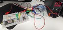
What you're seeing above is about the simplest circuit you can build in order to control a "dumb" 24 volt DC LED strip.
For the smart Prusa enclosure project I'm working on, I've been looking at alternatives to control the two loads (fan and lighting) that will go in the Prusa MK4 enclosure. I believe I have finally settled on the final components we'll use to drive the loads; we are going to use a MOSFET module for the energy-demanding loads in our circuit — the fan and the LED strip.
What's a MOSFET and why are they useful?
A MOSFET (short for metal-oxide semiconductor field effect transistor) is a sort of "amplifier of logic gates". You feed its low-voltage inputs with a small voltage that crosses a specified threshold, and they immediately open up to let a much higher voltage through their outputs. You cut the power to the inputs, and they shut off the higher voltage path. The control voltage is usually logic level (3.3 volts or 5 volts, with the control current in the milliamp range) but the controlled voltage and current can be much, much higher.
Why use a MOSFET? MOSFETs are very efficient (almost as efficient as relays). MOSFETs, unlike relays, are quiet— they don't click when they toggle. MOSFETs are routinely used to build modules where the low-voltage side and the high-voltage side are completely isolated, which makes the low-voltage side safe from any high voltage (the MOSFET we will be using is of that kind). Finally, many MOSFETs can react to power on and off very quickly (up to a megahertz range), which means you can use them as controllers for dimming lights or variable speed fans; if you've heard the term PWM, you can guess that MOSFETs are often what's driven using PWM.
Initially, I had decided I would use the very popular IRF520 module, depicted here:

This module is extremely popular, it supports very high currents and voltages, it's very efficient, and it's incredibly cheap. Practically everyone with an Arduino has used this thing. The catch? The logic level needed to activate this MOSFET module is 5 volts; that voltage is not something I could supply from a GPIO pin of my ESP32 device. I tried it; it didn't work.
So I searched for equivalent modules, and I ended up finding the D4184 MOSFET control module:

It's a super simple device. It's cheap. It can activate with 3.3 volts DC, which means I can use it directly from the ESP32 device. It demands only 2 milliamps of power from GPIO pin through control loop to ground. It can drive the LEDs and the fan I need easily. It's very small. The low- and high-voltage sides are optoisolated. And it's plug–and-play — I barely need to add any component to get this to work! No bring-your-own-transistor, no bring-your-own-resistor — it's ready to go.
Regrettably, mine came with the screw-on terminals not yet mounted... but that's nothing a bit of solder and flux can't fix.
Bill of materials
Since I will be reusing nearly all of the materials I used in the relay build, please refer to that post for details and suppliers of the parts.
Here's what you'll need for this build.
- An LED strip, 24 volts DC.
- A 24 volt DC power supply.
- An ESP32 device compatible with ESPHome.
- A 1N5819 Schottky diode.
- A MP1584EN / LM2596 DC-DC step-down converter from 24 volts to 3.3 volts.
- A breadboard, some loose wiring for breadboarding, and some alligator clip cables.
- The MOSFET module in question.
How is the circuit hooked up?
OK. Eager to find out the theory of operation? Let's first look at the wiring.
- Have your ESP32 already powered up (3.3 volts and ground).
- In this build we're using the same buck converter we used in our relay build. The relay build page contains detailed information on how to use the buck converter and the 24 volt power supply to power the ESP32 correctly.
- I think you mau be able to power your ESP32 via USB, so long as the ground between your ESP32 and your higher-voltage power supply is common.
- Make sure your ESP32 is programmed (see below for sample code).
- Connect ground (of your ESP and your circuit) to
GNDon the module, and a GPIO output pin from your ESP32 to thePWMterminal on the module.- The ESPHome programming sketch available below uses
GPIO27.
- The ESPHome programming sketch available below uses
- Then connect
+on the module to the positive terminal of a high voltage (up to 30 volts DC) source; once connected, connect your power source's negative terminal (the ground) to the-pin on the module. This completes the high voltage supply to the MOSFET module. - Connect your load negative to the
LOADpin on the module, and your load's positive to the high voltage supply's positive terminal. - Finally, connect the Schottky diode in "reverse", parallel to your load.
- The negative side of the diode goes to the high voltage power source positive.
- The positive side goes to the
LOADMOSFET module pin. - The Schottky diode is there to help dissipate any inductance from the load (should the load be like a motor or something similarly inductive). To quote the relevant explanation from the relay build: when the load de-energizes, if the load is inductive, it can dump a large voltage spike"backwards" onto the MOSFET circuitry (this is called back EMF); this can damage the module. With the diode there, under normal conditions current can't flow backwards across the diode and that's all fine, but when the load stops seeing input power and dumps its back EMF, the electricity flows through the diode back into the load, and this gets rid of the voltage spike.
The complete circuit diagram is here (and also attached to this post as PDF):

Here is a close-up of the MOSFET module pinout — you can contrast the wire color coding with the picture of the full build at the top of this post:
")
Programming your ESP32 to control the MOSFET module
This part assumes you have ESPHome installed and know how to use it. It's fairly easy once it's set up on your machine.
Here is a sample sketch. Create this as a new configuration in your ESPHome setup, then add the code below to the configuration (making sure to preserve the api and ota sections of the configuration you created). After doing so, flash it to your device via serial (your USB port) the first time. Subsequently, you can flash changes via Wi-Fi.
substitutions:
  name: mosfet-tester
  friendly_name: MOSFET tester

esphome:
  name: ${name}
  friendly_name: ${friendly_name}
  name_add_mac_suffix: false

esp32:
  # XTVTX ESP32 (wroom)
  board: nodemcu-32s
  framework:
    type: arduino

# Enable logging
logger:
  level: debug

# Enable Web.
# Turn me off and enable below.
web_server:
  port: 80
  include_internal: true
  local: true

# Enable Home Assistant API
# You'll use your own configuration's API section.
# api:
#   encryption:
#     key: ">API encryption key<"


# You'll use your own configuration's OTA section.
# ota:
#   password: ">OTA password<"

# The following will require you to have these two secrets
# in your ESPHome secrets file.
wifi:
  ssid: !secret wifi_ssid
  password: !secret wifi_password
  ap:
    ssid: ${friendly_name}
    password: password

button:
  - platform: restart
    name: Restart
    entity_category: diagnostic
    icon: mdi:restart
  - platform: safe_mode
    name: Safe mode restart
    entity_category: diagnostic
    icon: mdi:restart-alert

sensor:
- platform: wifi_signal
  name: "Wi-Fi signal strength"
  update_interval: 10s
  entity_category: "diagnostic"
- platform: internal_temperature
  name: "Device temperature"
  update_interval: 10s
  entity_category: "diagnostic"

output:
  - platform: gpio
    # D27 on chip.
    pin: GPIO27
    id: "out_1"

light:
  - platform: binary
    name: Camera light
    id: camera_light
    output: out_1
    icon: mdi:led-strip-variant
Assuming your Wi-Fi credentials were correct, then once the device is flashed, your device will appear in your local network with an IP address given by your router (assuming your home networking setup is like most everybody else's). ESPHome's log screen, which appears immediately after flashing the ESP32 device via USB, should give you the IP address to visit on your browser, but if you get nothing, try looking up the IP address of the device in your router's status or configuration pages.
If, after one minute, the device has yet to connect to Wi-Fi, then it will start up a captive portal you can access with your phone to input the Wi-Fi credentials for your wireless network. Use the captive portal to configure your wireless network into the ESP32 device, and try again.
Bonus exercise: can you turn the circuit into a dimmer? Yes, you can! In the output: section of the sketch, turn platform: gpio into platform: ledc. Then, in the light: section, change platform: binary to platform: monochromatic. Reflash your ESP32 device — you can now control the intensity of the LED strip with a slider!
Check out the circuit in action!
With the IP address of your ESP32 opened up in your browser at http://<the IP address>/, try flicking the light on and off:
What's going on here?
Now let's see how the build works. The circuit is not that dissimilar from our relay build, but let's go over a very simplified explanation of what's going on anyway:
- You flick the switch from Off to On.
- This causes the GPIO pin on your ESP32 to go HIGH.
- When the GPIO pin to HIGH, the base of the MOSFET gets excited, and it begins conducting high voltage between
LOADand and+of the MOSFET module. - Because of that, the LED strip powers on.
- You cut power from the ESP to the GPIO pin when you flick the switch from On to Off.
- The base of the MOSFET detects this, and shuts off the high voltage path.
- The LED strip powers off.
- The Schottky diode helps dissipate any inductance on the load.
If you have to TL;DR this sequence of operation, the MOSFET acts much like a relay would. There's an important distinction: unlike in the case of a relay-switched circuit, the low-voltage side sees no inductive reactance when the MOSFET shuts off. When we use the MOSFET, the concern about inductance exists on the high-voltage side.
Can I use this in Home Assistant?
Sure! This circuit is now ready to be added to Home Assistant:
- Go to the Devices & Services page in your Home Assistant settings, and you'll see the device has been discovered.
- Add it to Home Assistant, giving Home Assistant the API key you supplied in the ESPHome sketch you flashed to your ESP32.
- Now you can control your circuit directly from Home Assistant.


It's wireless-connected smart circuit time, fully compatible with Home Assistant. Follow along to build your own smart LED strip lighting at home.
A fine tutorial you can follow to build your own smart 3D printed enclosure. Electronics, ESPHome, Home Assistant and Creative Commons.