How to control a 24 volt LED strip using an ESP32 and ESPHome
It's wireless-connected smart circuit time, fully compatible with Home Assistant. Follow along to build your own smart LED strip lighting at home.

For the smart Prusa enclosure project I'm working on, I've been looking at alternatives to control the two loads (fan and lighting) that will go in the Prusa MK4 enclosure.
One of the alternatives is to use a relay to drive the LEDs and fan, all controlled by an ESP32 device. I didn't want to use a relay, and I still don't (I will likely end up using a MOSFET module, since MOSFETs are silent, and relays are not). That said, I still had to try the relay option, just to learn how it works.
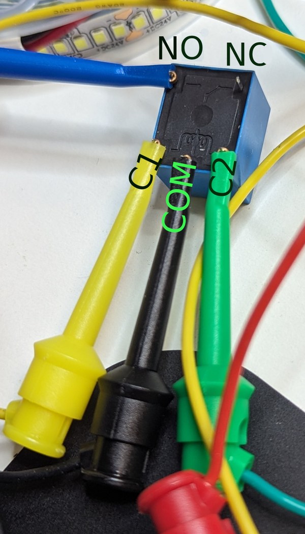
You use relays when you need on/off control of a high voltage or current, driven by a low voltage low current device (like an ESP32). The way a relay works is, it has an internal coil that moves a switch from "off" to "on" (connecting common pin COM to normally-open pin NO) when the coil is energized across its two pins C1 and C2 by the specified voltage, producing a satisfying click when this action happens. When the voltage across the coil is not there, some relays (of the SPDT — single pole dual throw — type) bridge COM to normally-closed NC.
This project will be built on ESPHome, and is therefore natively compatible with Home Assistant. In other words, the ESPHome sketch you will program on your ESP32 device should be immediately addable to your Home Assistant instance — you can control your LED strip directly from your Home Assistant dashboard.
I originally bought some relay modules (which come ready-to-be-plugged into an ESP32 device), but the weirdos who sold me the modules at AliExpress did not send me modules — they just sent me bare relays. So I had to make myself, with low-level components, the equivalent switching network to a relay module. I have laid out in detail why each component is necessary.
Bill of materials
Here's the bare minimum you'll need to get you started.
- An LED strip, 24 volts DC. I'm using this one.
- 12 volt strips will work too, but adjust your power supply.
- Make sure you buy LED strips that don't require a PWM driver. Quite a few on the market will need that. Relays can't do that. Generally, if a strip is specified to require a driver instead of a simple power supply, that strip can't be used here. An explainer on constant current vs. constant voltage can be read here.
- A 24 volt DC power supply.
- Make sure it has enough power to drive your LED strip (check the amperage rating, mine is 2 amps across all 5 meters) and the ESP32 device (0.2 amps).
- It's also possible to use a 12 volt supply, so long as your LED strip supports it.
- The supply must be constant voltage.
- In this demo, I'm using a bench power supply just to test, but any standard modern power supply should work.
- Do not power an LED strip that is rolled up for more than a few seconds. It will overheat. It must be unrolled first.
- An ESP32 device. I chose an XTVTX ESP32, commonly available on Amazon.
- Ensure the ESP32 you buy is compatible with ESPHome.
- A Schottky diode, part number 1N5819.
- A Sengled relay, part number SRD-03VDC-SL-C.
- A standard 2N2222 transistor. Amazon carries an assortment of transistors that carry it.
- A DC-DC step-down converter from 24 volts to 3.3 volts, to power the ESP32. I'm using an MP1584EN / LM2596, which looks like this.
- Usually these step-down converters can work with 12 volt supplies as well.
- A 200 ohm resistor. Resistor kits in AliExpress and Amazon carry it.
- A breadboard, some wiring to use with the breadboard, and some alligator clip cables. All of this is commonly available online.
- The schematic and code, supplied here.
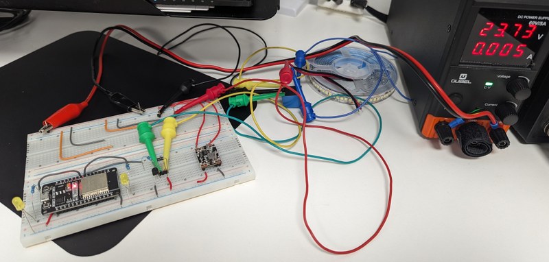
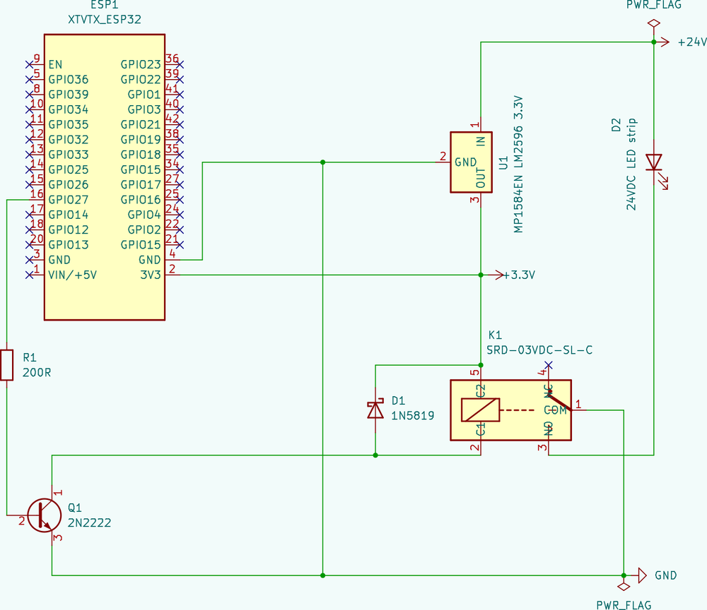
Here's the circuit schematic you'll have to hook up — it's explained in detail below, and attached to the bottom of this post as PDF as well.

In an electrical circuit schematic, green dots in crossing lines mean these lines are connected — when there is no dot in a crossing, those lines are not connected.
First, the basics:
- The ESP32 device needs power, so connect the positive out of the LM2596 converter to the
3V3pin on the ESP32. Connect the ESP32GNDpin to negative out (this is also ground). - Connect the LM2596 converter positive in (has a plus) to 24 volts, and the converter's negative in (has a minus) to ground.
- With that, you have power on the chip. You should be able to program and test it now — use the ESPHome software sketch below.
Be careful! Do not mistake the input for the output — you'll fry the converter (ask me how I learned this!) Remember: the converter input takes 24 volts, and the output produces 3.3 volts. The input goes to the supply, the output goes to the ESP32 voltage pin.
Now, the switching network. This network runs exclusively at 3.3 volts; the circuit for switching is composed of the resistor, the transistor, the Schottky diode and the relay module. The general way it works is:
- Your ESP32 device produces a 3.3 volt output, which (current-limited by the resistor) excites the base of the transistor.
- Once the transistor is excited, it "opens the door" for electricity to flow between its other two legs.
- One of the legs of the transistor is hooked to ground, and the other is attached to one side of the coil of the relay — the other side of the relay coil will be powered by 3.3 volts.
- So, when the transistor is open (by orders of the ESP32), 3.3 volts pass from the 3.3 volt source through the relay coil to ground — switching the relay on.
- Finally, a Schottky diode is needed (connected "backwards") on the two legs of the relay coil, because when the coil de-energizes, not only can arcing inside the relay occur, it can dump a large voltage spike"backwards" onto the transistor (this is called back EMF); this can fry the transistor. With the diode there, under normal conditions current can't flow backwards across the diode and that's all fine, but when the coil dumps its back EMF, the electricity flows through the diode back into the coil, and this gets rid of the voltage spike.
Here's how you wire this up:
- Connect GPIO27 on the ESP32 device to one side of a 200 ohm resistor.
- This resistor is needed to ensure that only 10 mA of current go out the GPIO pin, otherwise you'd fry the ESP32 device shortly.
- Yes, I did measure the current — only 10 mA, well within the specifications of what the ESP32 can deliver through GPIO.
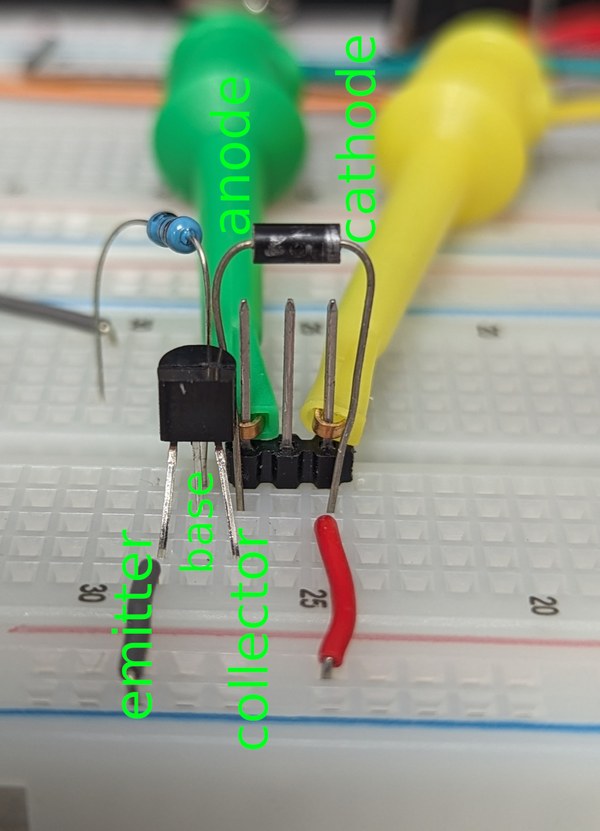
- The other side of the resistor goes to the base of the 2N2222 transistor — the base is the middle leg.
- Connect the emitter of the transistor to ground. If you look at the transistor directly at its "flat face", the emitter is the left leg.
- Connect the collector (the right leg) of the transistor to:
- the anode of the Schottky diode (the side that has no grey stripe), and
- pin
C1on the relay.
- Connect the relay pin
C2to:- the cathode of the Schottky diode (the side that has a grey stripe), and
- the 3.3 volt rail also connected to the ESP32
3V3pin.
Here is an annotated close-up of the transistor and the Schottky diode, and how they should be wired up:

And here is an annotated picture of the relay (upside down, on its belly):

That completes the switching network.
Finally, the load network. This one runs at 24 volts:
- Connect the
COMpin on the relay to the ground of your circuit. - Connect the
NO(normally open) pin on the relay to the negative wire of your LED strip.- This pin is always disconnected, so the circuit is open, when the relay is not energized.
- Connect the positive wire of your LED strip to the 24 volt rail of your power supply.
That's it!
Programming your ESP32
This part assumes you have ESPHome installed and know how to use it. It's fairly easy once it's set up on your machine.
Here is a sample sketch. Create this as a new configuration in your ESPHome setup, then add the code below to the configuration (making sure to preserve the api and ota sections of the configuration you created). After doing so, flash it to your device via serial (your USB port) the first time. Subsequently, you can flash changes via Wi-Fi.
substitutions:
  name: relay-tester
  friendly_name: Relay tester

esphome:
  name: ${name}
  friendly_name: ${friendly_name}

esp32:
  # XTVTX ESP32 (wroom)
  # You may have to change this if the ESP32 device
  # you bought is a of different type.
  board: nodemcu-32s
  framework:
    type: arduino

# Enable logging
logger:
  level: debug

# Enable anonymous Web control.
web_server:
  port: 80
  include_internal: true
  local: true

# Enable Home Assistant API
# You'll use your own configuration's API section.
# api:
#   encryption:
#     key: "<api encryption key>"

# You'll use your own configuration's OTA section.
# ota:
#   password: "<OTA password>"

# The following will require you to have these two secrets
# in your ESPHome secrets file.
wifi:
  ssid: !secret wifi_ssid
  password: !secret wifi_password
  ap:
    ssid: ${friendly_name}
    password: password

button:
  - platform: restart
    name: Restart
    entity_category: diagnostic
    icon: mdi:restart
  - platform: safe_mode
    name: Safe mode restart
    entity_category: diagnostic
    icon: mdi:restart-alert

sensor:
- platform: wifi_signal
  name: "Wi-Fi signal strength"
  update_interval: 10s
  entity_category: "diagnostic"
- platform: internal_temperature
  name: "Device temperature"
  update_interval: 10s
  entity_category: "diagnostic"

output:
  - platform: gpio
    pin: GPIO27
    id: "out_1"

light:
  - platform: binary
    name: Camera light
    id: camera_light
    output: out_1
    icon: mdi:led-strip-variant
Assuming your Wi-Fi credentials were correct, then once the device is flashed, your device will appear in your local network with an IP address given by your router (assuming your home networking setup is like most everybody else's). ESPHome's log screen, which appears immediately after flashing the ESP32 device via USB, should give you the IP address to visit on your browser, but if you get nothing, try looking up the IP address of the device in your router's status or configuration pages.
If, after one minute, the device has yet to connect to Wi-Fi, then it will start up a captive portal you can access with your phone to input the Wi-Fi credentials for your wireless network. Use the captive portal to configure your wireless network into the ESP32 device, and try again.
Time to see it in action!
Once you have the IP address of your ESP32 device, visit the Web site http://<the IP address>/. This is how the whole thing will look like in action:
The sample you see on video has some differences from what you'll get in the sample sketch. For example, you'll get Camera light, but you won't get Camera light switch, since the sketch I pasted above is simplified to just control the LED strip.
So what's going on here?
- The switch onscreen is flicked to on. This goes through Wi-Fi to the ESP32.
- The ESP32 sends a signal to the transistor.
- The transistor, in turn, activates the relay.
- When the relay activates, 24 volts flow through it, and that causes the LEDs to flick on.
- When the switch is flicked off, the opposite happens, and the relay deactivates.
- As the coil in the relay, deactivates, a large back EMF spike (microseconds in duration) is sent by the relay in the opposite direction.
- The Schottky diode aids in dissipating it to protect your ESP32 and your transistor.
- Once the relay coil is fully deactivated, the LEDs turn off
And that concludes our adventure!


