 Wiring diagram to flash Sinilink XY.jpg
Switching an USB load on or off using the Sinilink XY-WFUSB and ESPHome
It's both really amazing, and it was easier than I thought!

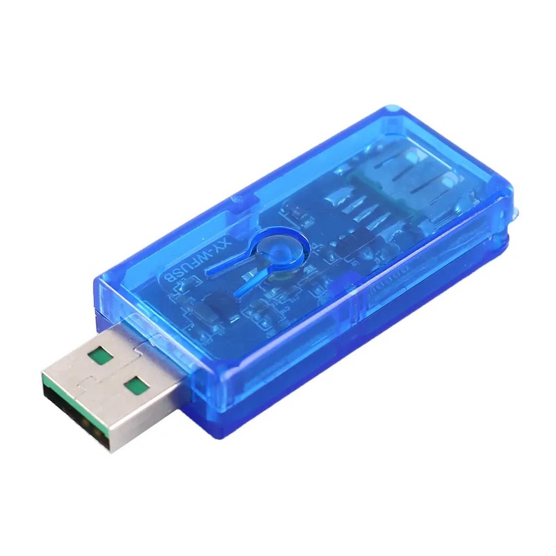
The Sinilink XY-WFUSB device lets you switch a USB-powered device on or off via Wi-Fi. It has an ESP chip and is — according to the video below — capable of routing USB power delivery (id est, more than 5 volts and 1 amp).
By default it comes with a proprietary app to govern it.
I liberated mine by installing ESPHome. Here are my notes on the device.
How to pry the case open
The case is not glued, but it is firmly put together in a friction fit by six pins and matching holes.
Using a really thin flat screwdriver, pry your way into the seam at the edge near one of the six pins, then turn the screwdriver gently to leverage your way into pulling the pin out of its matching hole. Do this near each one of the five other pins, until the case pops open.
After that, the device comes out easily.
How to wire the device up

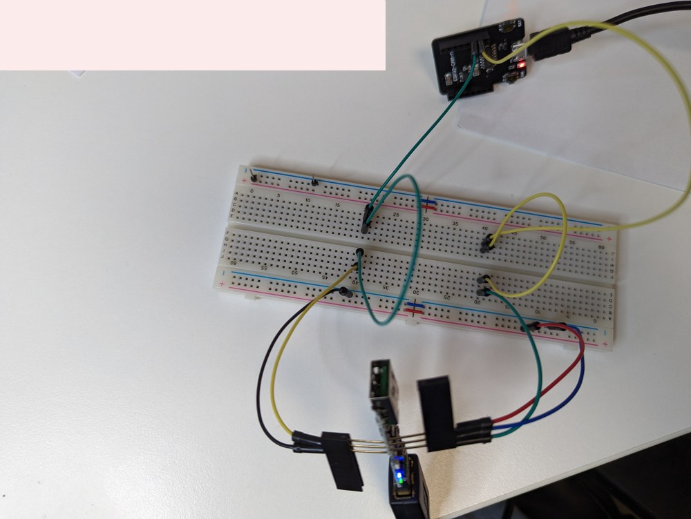
Wiring the device is tricky. The pin holes are tiny. You must use really thin electronics or sewing pins. Nonetheless, as you can see from the photo, it's doable — I had these pins that were nominally 1mm wide, but much thinner in the other dimension, so that worked out for me. Worst case scenario, you'll have to solder very thin cables (think stripped Ethernet wire) onto each hole. Make sure the connections are sturdy in any case.
I used an ESP_CAM_MB serial converter to do the job of flashing it, so that's what you see wired there. Wiring consists of doing the following (at the very minimum):
- Connect the RX hole of the device to the TX pin of your serial converter.
- Connect the TX hole of the device to the RX pin of your serial converter.
- Connect the GND hole of the device to your common ground.
- Connect the GPIO0 hole of the device to your common ground.
- Connect your serial device's ground pin to your common ground.
Here is a ghetto schematic of the pinout of the ESP_CAM_MB board when seen from above (with the micro-USB female port pointing down). I could not find a photo of its pinout, but this is the pinout reverse engineered from the pinout of its ESP32 daughterboard, the ESP_CAM board.
( )          ( ) <- 3.3V supply (you won't get voltage out of this)
( )          ( )
( )          ( )
( )          ( ) <- ground
( )          ( )
( )          ( ) <- TX (on board, on ESP_CAM daughterboard is GPIO3 RX)
( )          ( ) <- RX (on board, on ESP_CAM daughterboard is GPIO1 TX)
( )          ( ) <- ground
micro-usb female port
Find in the following link a photo of the pinout of the Sinilink device, followed by a ghetto schematic of its pinout:
usb female port
push button is on the other side of the board
( )          <- 3v3
( )          <- rst
( )          <- gpio0
( )          <- rx
( )          <- tx
( )          <- gnd
usb male port
Powering the devices: you must supply the device with power, and you must also supply the serial converter with power. In my project, I simply powered the Sinilink USB device with an USB extension cord (power-only is what I had at hand), while powering the ESP_CAM_MB device with an USB type A to micro-USB data cable. Both devices will then be getting the necessary 5 volts, and (in my case) both devices will downstep to 3.3 volts, thereby being able to communicate safely at the 3.3 volt expected on the serial pins / ports. Because I supplied power to both devices via USB, both are connected to the same 5 volt source and the same common ground, and therefore (as you can see in the photo) neither of the devices have their ground pins connected to any other ground.
Power the Sinilink device after powering your serial converter!
If you hooked everything up right, when you power your Sinilink device, both the green and the blue LEDs should be on — indicating it's ready to flash.
The software to flash
As mentioned before, I used an ESPHome program listing. Here is a sample (minus the marked secrets which you must substitute):
substitutions:
  name: "ipad-charge-controller"
  name_underscored: ipad_charge_controller
  friendly_name: iPad charge controller

esphome:
  name: ${name}
  name_add_mac_suffix: false
  friendly_name: ${friendly_name}
  platform: ESP8266
  board: esp01_1m

api:
  encryption:
    key: !secret encryption_key

logger:
  level: debug

ota:
  password: !secret ota_password

wifi:
  ssid: !secret wifi_ssid
  password: !secret wifi_password
  manual_ip:
    # I am using static IPs here.  You may want to
    # omit this section altogether.
    static_ip: 10.250.1.18
    gateway: 10.250.1.1
    subnet: 255.255.255.0

button:
- platform: restart
  name: Restart
  entity_category: diagnostic
  icon: mdi:restart
- platform: safe_mode
  name: Safe mode restart
  entity_category: diagnostic
  icon: mdi:restart-alert

# Blue LED
status_led:
  pin:
    number: GPIO16

switch:
  # Relay
  - platform: gpio
    id: relay
    pin: GPIO5

  # Green LED
  - platform: gpio
    pin: GPIO14
    id: green_led
    inverted: true # start on

  # Switch template to link relay and green LED states
  # LED is on when relay is off
  - platform: template
    id: ${name_underscored}_switch
    name: Switch
    lambda: |-
      if (id(relay).state) {
        return true;
      } else {
        return false;
      }
    turn_on_action:
        - switch.turn_on:
            id: green_led
        - switch.turn_on:
            id: relay
    turn_off_action:
        - switch.turn_off:
            id: green_led
        - switch.turn_off:
            id: relay

# Button
binary_sensor:
  - platform: gpio
    id: ${name_underscored}_button
    pin:
      number: GPIO04
      mode: INPUT_PULLUP
      inverted: True
    on_press:
      - switch.toggle: "${name_underscored}_switch"
Use ESPHome to flash this program listing after making the necessary modifications.
Once you are done flashing, ESPHome will fail to get the logs from the device. What you must do now is:
- disconnect the Sinilink device from power,
- disconnect the device from the serial converter,
- disconnect the GPIO0 hole from ground,
- reconnect the device back to power.
You will note that now only the green LED turns on steady after boot — the blue LED no longer turns on (because the device is no longer in flashing mode. At this point, you will be able to get to the device's logs wirelessly using ESPHome (assuming your Wi-Fi router gave the device an address, and everything else worked out okay on your side). And, of course, you will also be able to flash the device over the air from this point on.
So what does this program listing do?
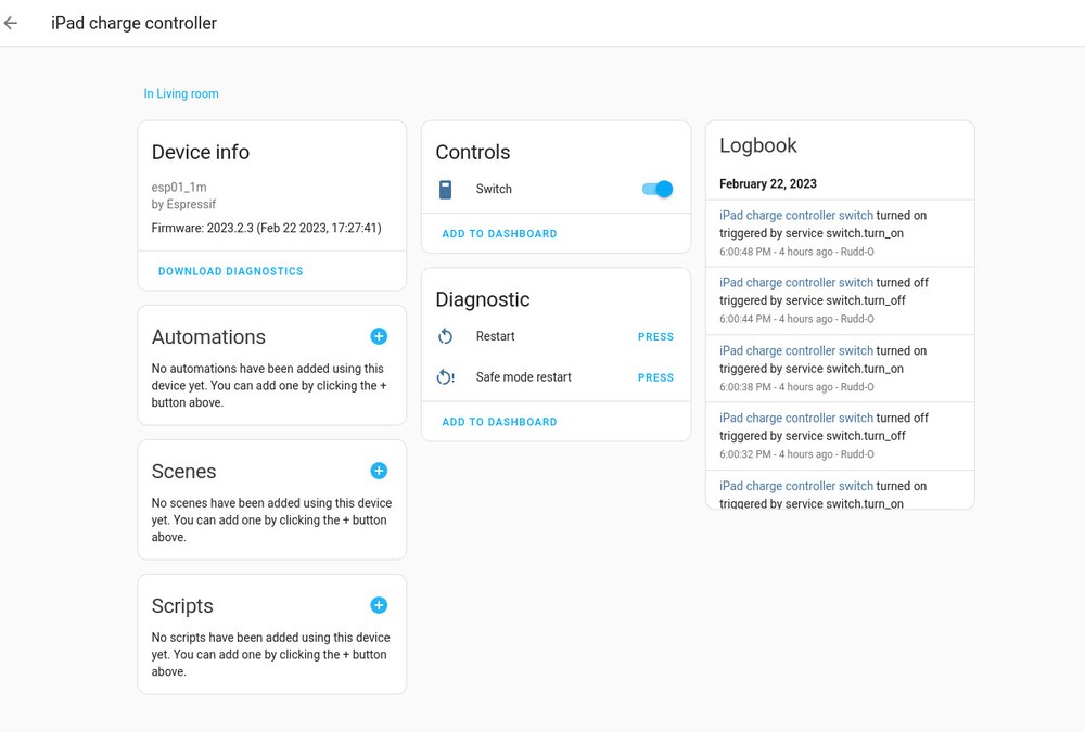
It gives you a device with one physical control and three software controls (accessible via Home Assistant):
- the physical button on the Sinilink toggles power on the USB device connected to the Sinilink's female port,
- two button entities, one for restart and another for safe restart, are available via Home Assistant,
- a switch entity will be available via Home Assistant that lets you do exactly the same as the physical button, only over Wi-Fi.

Done flashing?
Patch the device up together in its case! It's very easy and you can't make a mistake there — the board only fits one way within both sides of the case. Make sure to line up the push button notch in one side of the case with the actual push button in the device. Then press together. Presto!
What's this good for?
It's really neat! From the program listing you may have surmised I'm using this as a charge controller for my iPad, since I would like its battery not to bite the dust. Coupled with a very simple automation, I'm ensuring that my iPad never goes above 75% and never below 65%, as per this document.
In general, you can use this device, as programmed, to create automations that control the charge cycles of your USB-powered devices. You can also use this device as relay to switch off USB-powered devices that don't have a battery. Of course, the device has one more GPIO, which you can use in both on/off and PWM mode — feel free to experiment with it.
 Wiring diagram to flash Sinilink XY.jpg
 Screenshot 2023-02-22 at 22-25-20 Settings – Home Assistant.jpg

